Heatpump Controls
The Functional Profiles for the heat pumps are organized in a modular way. The manufacturer decides, which Functional Profiles will be implemented in the Product EID. The HeatPumpBase profile as well as the energy monitoring profile must be implemented, the others are optional.
The low level profiles are listed on the left side of Fig. 4, consisting of the level 1 and level 2 profiles as well as the energy monitoring profile. The level 1 profile represents a simple on/off switching according to the lock time of the grid operator (“EVU Sperre”). The level 2 profile represents a switching of 4 states according to the SG-Ready standard according to bwp (“Bundesverband Wärmepumpen Deutschland”) which is closer described in the following link:
https://www.waermepumpe.de/normen-technik/sg-ready/
Here, a one-directional implementation on level 2 is implemented (with writing of the states only) and a bi-directional implementation on level 2m (with reading of the states also).
The energy monitoring profile is on level “m” and provides “read-only” data for monitoring purpose, such as energy data an run times. It may be used for Minergie® Monitoring or other applications.
The high level profiles are listed on the right side. Currently they are on level 4, which means that a dynamic changing of setpoints is possible. As mentioned, the manufacturer must provide the HeatPumpBase profile, which contains some basic Data Points for setting and reading the operation mode of the heat pump as well as reading basic data. Note that the operation mode is typically controlled by the heat pump itself (e.g. “heating”, “hot water production”, “cooling”, etc.). However, it may also be set externally.
The profiles below represent modules of the hydraulic system. These modules are described in the Section below.
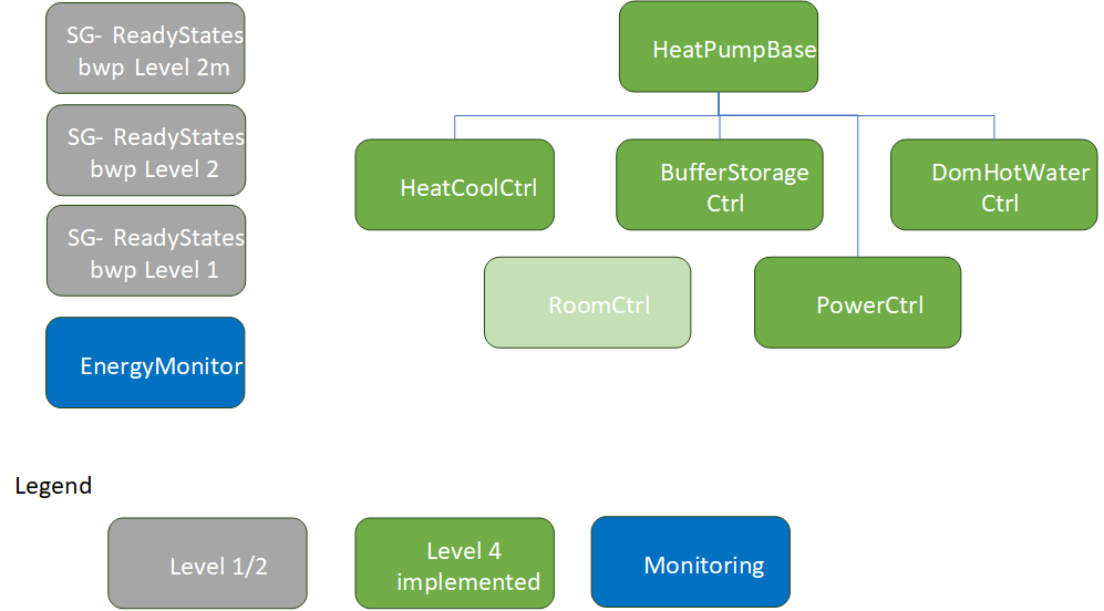
Fig. 4 Heat Pump Functional Profiles
Heat Pump Functional Profiles in Hydraulic Scheme (General Overview)
The HeatCoolCtrl profile provides Data Points for a hydraulic heating or cooling cycle. There may exist one or several of these profiles for each cycle in a real plant. Generally the heating cycles provide hot water to the building. They can also run as cooling cycles, when the heat pump is in cooling mode. For regulating the supply temperature, mixing valves are installed. In larger buildings, several heating cycles with distinct mixing valves may be installed to provide different supply temperature levels for the groups (“Mischgruppen”). Each HeatCoolCtrll profile controls the temperature of one group. With this profile, the setpoints of the supply temperatures may be influenced. For example more heat may be provided to the building by increasing the setpoint (which results to a thermal storage of energy in the building mass).
The BufferStorageCtrl profile provides Data Points for a hydraulic buffer storage tank. Typically one buffer storage tank exists. With this profile, the temperature setpoint of the buffer storage tank may be influenced. A typical application is the increase of the storage temperature at local PVA production in order to optimize self-consumption. If the temperature of the buffer storage tank is increased, there is no direct effect on the building in typical installations (when mixing valves are installed). In special installations, no buffer storage tank may exist (in combination with floor heating systems). Then, no distinct control is possible.
The DomHotWaterCtrl profile provides data points for a hydraulic hot water tank for domestic water (tap water, “Brauchwarmwasser”). Typically one domestic hot water storage tank exists. With this profile, the temperature setpoint of the storage tank may be influenced. A typical application is the increase of the storage temperature at local PV production in order to optimize self-consumption.
Some heat pump manufacturers provide an additional PowerCtrl profile. With this profile the electric power consumption of a heat pump may be influenced directly. For example, the compressor speed may be influenced. Note that the control of the compressor has a main effect on the lifetime of this part. Running at high speed for long time may lead to over-heating. Running at low speed may result in reduced lubrication. That’s why the manufacturers are cautious in providing these profile, even if it is most attractive for an effective energy management. Some manufacturers do not provide the profile at all, other manufacturers provide the influence of the compressor speed in some operation modes only (e.g. domestic hot water production). Some restrictions are noted in the profile as explaining text. In order to be sure, always contact the manufacturer in order get the latest information.
On the other hand, the PowerCtrl profile itself has a limited effect due to the temperature setpoints. For example, the compressor stops when the hot water tank reaches the maximum temperature. Therefore it is recommended to control the temperature setpoints as well, using the DomHotWaterCtrl (or BufferStorageCtrl) profile.
The following Sections show some manufacturer specific implementations of the hydraulic modules.
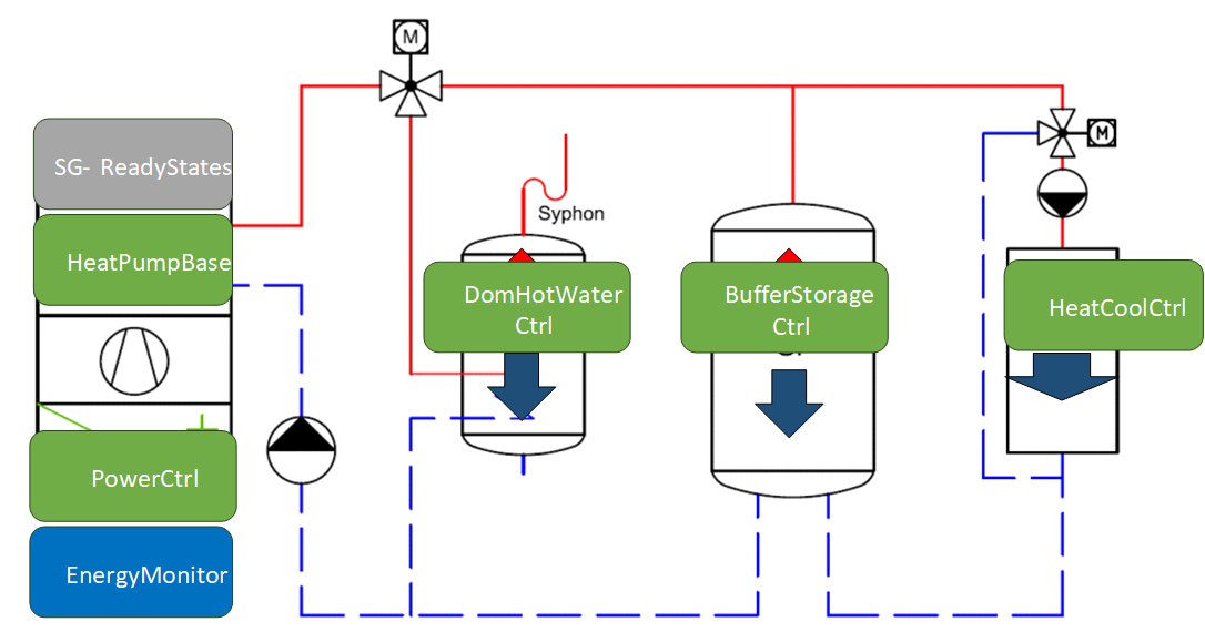
Fig. 5 Heat Pump Functional Profiles Scheme
HeatCoolCtrl Functional Profile
In the HeatCoolCtrl profile the CEM may choose how to control the heat pump. There are the following two ways:
Indirect Comfort Control (recommended for typical CEM applications).
With this control mode, the CEM only sets the comfort setpoint (SetpointComfort, e.g. 20°C for room heating). The internal heat pump controller then calculates the supply water temperature setpoint from the heating curve and controls the mixing valve of the corresponding heating circuit . The heating curve is set during commissioning from the HVAC specialist according to the building and heating system. Typically, the heat pump provides a comfort and eco setpoint at different temperature levels (SetpointComfort, SetpointEco). The comfort and eco setpoints may be switched by choosing the corresponding operation mode. In program/automatic mode, the heat pump itself switches the setpoints
by an internally defined time schedule (e.g. for temperature lowering during the night).
By increasing or decreasing the comfort (or eco) setpoint the amount of energy transferred to the building may be influenced by the CEM. This is an easy way to store thermal energy in the building mass. To stay in the comfort zone, the SetpointComfort signal should be controlled in a small range (e.g. 20°C - 23°C). Also the effect of energy storage depends on the heating distribution system and optional room control (which cannot be influenced by the HeatCoolCtrl profile). Once changed set points through the CEM stay changed unless the CEM sets the value back to the original value.
The advantage of this control mode is the separation of the internal HVAC settings of the heat pump from external energy management. No internal parameters such as the gradient of the heat curve, heating/cooling limits, etc. will be changed. Therefore, no HVAC expert knowledge is required for control. The effect is the same as the end-user would change the desired comfort temperature at the interface of the heat pump controller.
Direct Supply Water Temperature Control (for HVAC specialists or BA systems only).
With this control mode, the CEM directly controls the supply temperature setpoint (SupplyWaterTempStpt, e.g. 35°C for a floor heating system). It bypasses the heat curve of the internal heat pump controller and therefore must implement the HVAC/building characteristics itself. The internal heat pump controller only controls the mixing valve of the corresponding heating circuit for the given setpoint. For this use case, the heat pump needs to be set to a special “direct control mode” (which is also called “external control” at some manufacturers).
This control mode is only used for building automation (BA) systems or special CEM systems which implement their own HVAC logic for large applications. Therefore, deep HVAC expert knowledge is required.
Direct Supply Water Temperature Control vs. Indirect Comfort Control
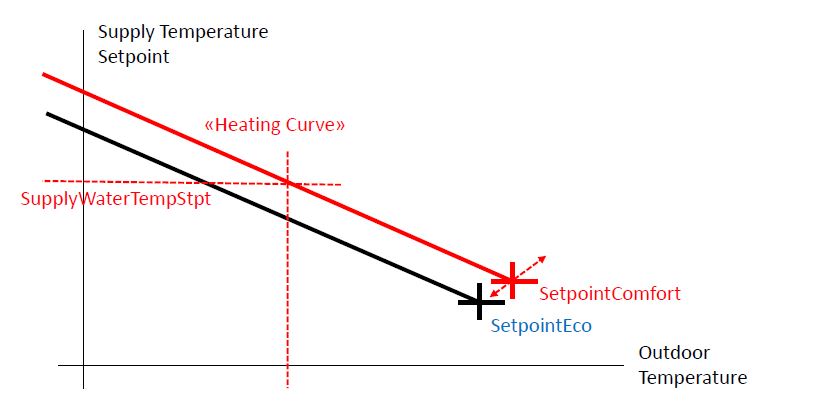
Fig. 6 Heating Curve
Heat Pump Functional Profiles in Stiebel Eltron Product (EID)
This section shows the implementation of the term:Functional Profiles for heat pumps of Stiebel Eltron®. Note that Stiebel Eltron heat pumps are controlled over an additional gateway, called “ISG” (internet service gateway). The ISG must be delivered with an appropriate software version providing Modbus communication:
ISG web Regelung / Energiemanagement von STIEBEL ELTRON (stiebel-eltron.ch)
Contact the manufacturer to get more information.
Varying from the general scheme above, the assignment of the HeatCoolCtrl profiles are different. Here the HeatCoolCtrl profile 1 represents the “charging cycle” for the buffer storage (“Ladekreis”). With this profile the “charging temperature” may be influenced. On the other hand, the HeatCoolCtrl profile 2 represents the “discharging cycle” to the building (“Entladekreis”). With this profile, the supply temperature to the building may be influenced. Typically, a mixing valve is installed to control the supply temperature.
Also Stiebel Eltron does not provide any PowerCtrl profile at the time (March 2024) because of the reasons mentioned above.

Fig. 7 Heat Pump Functional Profiles Scheme
Heat Pump Functional Profiles in CTA Product (EID)
This section shows the implementation of the functional profiles for heat pumps of CTA®. Note that only the CTA “Inverta” heat pumps with inverter control may be controlled over Modbus TCP at the time (March 2024). They don’t need any additional hardware for connecting over LAN. Contact the manufacturer to get more information.
The CTA scheme corresponds to the general scheme above, but provides two HeatCoolCtrl profiles to control different heating groups (“Mischgruppen”) with separate mixing valves. With each HeatCoolCtrl profile, the supply temperature of one group may be influenced. Both the BufferStorageCtrl an HotWaterCtrl provide a way to increase temperature in order to optimize self-consumption.
In addition, CTA provides a PowerCtrl profile with which the compressor speed may be directly controlled. But as a restriction, it may only be controlled in one single operation mode for domestic hot water (state: March 2024). The actual operation mode is provided by the HeatPumpBase profile.
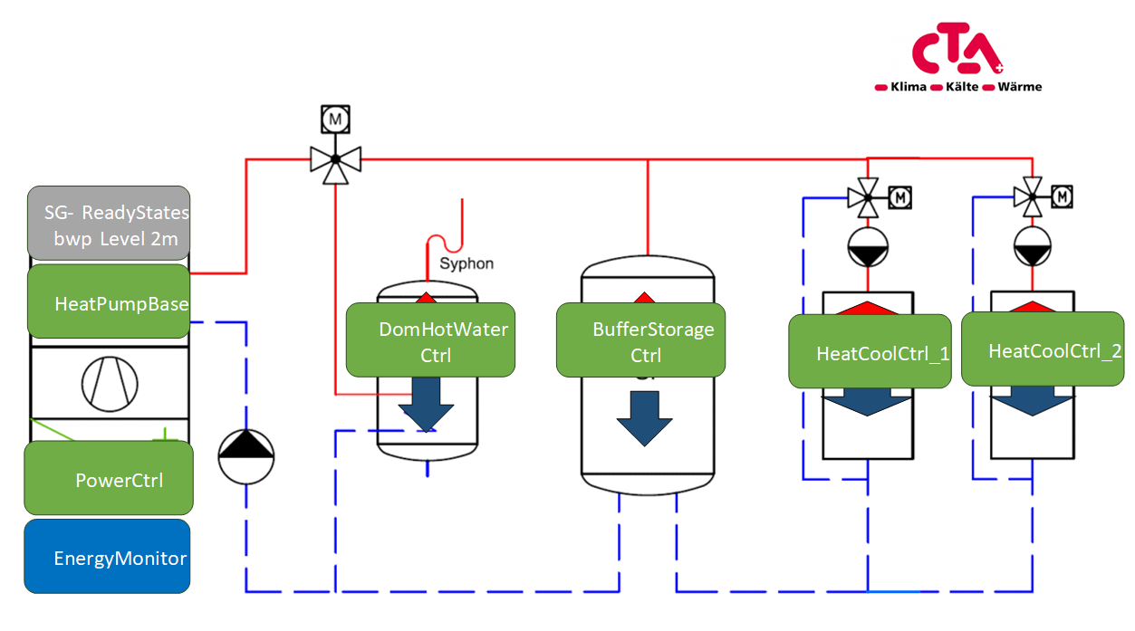
Fig. 8 CTA Heat Pump Functional Profiles Scheme
Heat Pump Functional Profiles in Hoval Product (EID)
This Sections shows the implementation of the functional profiles for heat pumps of Hoval®. Contact the manufacturer to get more information of the hardware required.
The Hoval scheme corresponds to the general scheme above, but provides three HeatCoolCtrl profiles to control different heating groups (“Mischgruppen”) with separate mixing valves. With each HeatCoolCtrl profile, the supply temperature of one group may be influenced. Both the BufferStorageCtrl an DomHotWaterCtrl provide a way to increase temperature in order to optimize self-consumption.
In addition, Hoval provides a PowerCtrl profile with which the power consumption of the compressor may be directly controlled (or at least a desired power consumption may be set). The power may be controlled in all operation modes (state: March 2024).
CHECK WITH MANUFACTURER IF TRUE !!
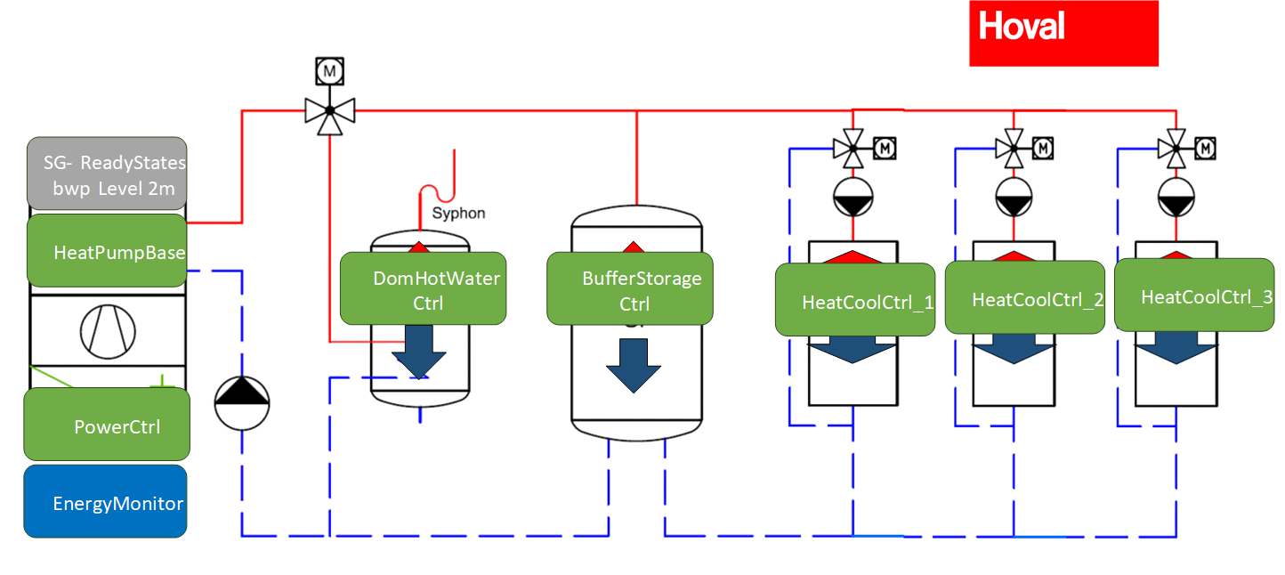
Fig. 9 Hoval Heat Pump Functional Profiles Scheme