Product Description File


Introduction
The Product Description File contains the information needed to describe the Product and use it through the generic SmartGridready API.
This allows potential Communicator devices such as EMS to easily integrate, implement, or access any SmartGridready certified product through a standardized set of functionalities.
The Product Description File contains:
General information about the Product such as product name, description or the product supplier.
The configuration parameters needed to operate the product.
The communication interface/protocol that is used to read values from and control the Product. Supported interfaces/protocols are:
Modbus
Http/REST
MQTT
The Functional Profiles that are supported by the Product
The Data Points that are provided by the Product
Fig. 12 shows the structure of a Product Description File:
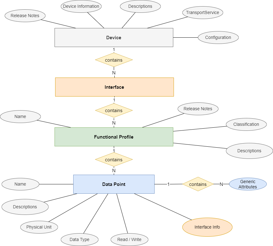
Fig. 12 Product Description File Structure
The Product Description File is an XML file, defined by the SmartGridready XML Schema (XSD) which builds the core of the SmartGridready Specification. You find the according resources on Github within SmartGridready project SGrSpecifications:
SGr XML Schema (XSD): Schema Database.
Product Description File content
The following chapters describe the term:Product Description File (EID) content und and are intended provide a guide for EID creators.
General Information
This chapter describes the XML elements that provide general information
<deviceName>
The name and optionally the model of the device.
Example:
<deviceName>
  CLEMAP Energy Monitor
</deviceName>
<manufacturer>
The name of the manufacturer
Example:
<manufacturer>
  CLEMAP
</manufacturer>
<releaseNotes>
The publication status and release version of the EID, together with the publisher.
Example:
<releaseNotes>
  <state>Published</state>
  <changeLog>
      <version>1.0.0</version>
      <date>2024-01-24</date>
      <author>Jane Doe, Acme</author>
      <comment>Published</comment>
  </changeLog>
</releaseNotes>
<deviceInformation>
Common device information, together with a legible description.
Explanations of specific child elements:
<legibleDescription>: The CDATA[[]] container allows formatting text with HTML syntax. This is used for the Product description text in the SGr library.
<deviceCategory>: The device category consists of an enumerated list of device categories inherited from the EEBUS specification.
<levelOfOperation> see Level of Operation
Example:
<deviceInformation>
  <legibleDescription>
    <textElement>CDATA[[Some device description ... <p> ... ]]</textElement>
    <language>de</language>
    <uri>https://www.clemap.com/...</uri>
  </legibleDescription>
  <deviceCategory>
      SubMeterElectricity
  </deviceCategory>
  <isLocalControl>false</isLocalControl>
  <softwareRevision>1.0.0</softwareRevision>
  <hardwareRevision>1.0.0</hardwareRevision>
  <manufacturerSpecificationIdentification>
      CLEMAP
  </manufacturerSpecificationIdentification>
  <levelOfOperation>m</levelOfOperation>
  <versionNumber>
    <primaryVersionNumber>1</primaryVersionNumber>
    <secondaryVersionNumber>0</secondaryVersionNumber>
    <subReleaseVersionNumber>0</subReleaseVersionNumber>
  </versionNumber>
  <testState>Verified</testState>
</deviceInformation>
Configuration List
<configurationList>
The configuration list element lists the configuration values that must be provided for EID when installing/instantiating a device.
Each configuration value listed in the configuration values has somewhere a placeholder with the same name in the EID which is replaced with the configuration value when installing/instantiating a device using the EID.
As an example, the configuration entry:
<configurationListElement>
  <name>ipaddress</name>
  <dataType>
    <string/>
  </dataType>
</configurationListElement>
corresponds to a placeholder {{ipaddress}} used elsewhere in the EID. This placeholder will be replaced
with the actual configuration value during installation or instantiation.
This convention enables the use of the same EID for multiple device instances by parameterizing instance-specific values.
Example:
<configurationList>
   <configurationListElement>
     <name>ipaddress</name>
     <dataType>
       <string/>
     </dataType>
     <configurationDescription>
       <textElement>Device IP address</textElement>
       <language>en</language>
       <label>IP Address</label>
     </configurationDescription>
     <configurationDescription>
       <textElement>IP Adresse des Gerätes</textElement>
       <language>de</language>
       <label>IP Adresse</label>
     </configurationDescription>
   </configurationListElement>
   <configurationListElement>
</configurationList>
Interface List
The interface list element lists the communication interfaces supported by the Product.
Supported Interfaces
Modbus
RTU, RTU-ASCII, modbus over serial interface RS232 and RS485.
TCPIP, TCPIP-ASCII
UDPIP, UDPIP-ASCII
REST-API HTTP, HTTPS
Messaging MQTT
For Modbus interfaces, the basic <interfaceList> is structured as follows:
<interfaceList>
    <modbusInterface>
        <modbusInterfaceDescription>
            ...
        </modbusInterfaceDescription>
        <modbusAtttributes>
            ...
        </modbusAttributes>
        <functionalProfileList>
            ...
        </functionalProfileList>
    </modbusInterface>
</interfaceList>
<modbusInterfaceDescription>describes the details needed to setup the communication with the Modbus device. See <modbusInterfaceDescription>.<modbusAttributes>contains optional attributes that describe additional modbus properties that might be needed to operate. See <modbusAttributes>.<functionalProfileList>. Contains a list of functional profiles supported by the Modbus interface. See <functionalProfileList>
For REST-API interfaces, the basic <interfaceList> is structured as follows:
<interfaceList>
     <restApiInterface>
         <restApiInterfaceDescription>
         ...
         </restApiInterfaceDescription>
         <functionalProfileList>
         ...
         </functionalProfileList>
     </restApiInterface>
</interfaceList>
<restApiInterfaceDescription>describes the details needed to setup the communication with the WEB-/REST- service . See <restApiInterfaceDescription>.<functionalProfileList>. Contains a list of supported functional profiles supported by the REST-API interface. See <functionalProfileList>.
For Messaging interfaces, the basic <interfaceList> is structured as follows:
<interfaceList>
    <messagingInterface>
        <messagingInterfaceDescription>
        ...
        </messagingInterfaceDescription>
        <functionalProfileList>
        ...
        </functionalProfileList>
    </messagingInterface>
</interfaceList>
<restApiInterfaceDescription>describes the details needed to setup the communication with the Messaging service such as an MQTT message broker. See messagingInterfaceDescription.<functionalProfileList>. Contains a list of supported functional profiles supported by the REST-API interface. See <functionalProfileList>
Note
The current Communication Handler libraries SGrJava and SGrPython do support only
one interface listed within the <interfaceList>.
<modbusInterfaceDescription>
The following basic modbus types can be selected:
RTU - binary data communication via serial interface RS232 or RS485
RTU-ASCII - communication via serial interface RS232 or RS485 using ASCII characters
TCPIP - binary data communication via TCP-IP connection
TCPIP-ASCII - communication via TCP-IP connection using ASCII characters
UDPIP - binary communication via UDP IP connection
UDPIP-ASCII - comunication via UDP IP connection using ASCII characters
For Modbus RTU and Modbus RTU-ASCII the <modbusInterfaceDescription> element is structured as follows (sample for
Modbus RTU):
<modbusInterfaceDescripion>
    <modbusInterfaceSelection>RTU</modbusInterfaceSelection>
    <modbusRtu>
          <slaveAddr>{{slave_id}}</slaveAddr>
          <portName>{{serial_port}}</portName>
          <baudRateSelected>{{serial_baudrate}}</baudRateSelected>
          <byteLenSelected>{{serial_databits}}</byteLenSelected>
          <paritySelected>{{serial_parity}}</paritySelected>
          <stopBitLenSelected>{{serial_stopbits}}</stopBitLenSelected>
          <serialInterfaceCapability>
            <baudRatesSupported>1200</baudRatesSupported>
            <baudRatesSupported>2400</baudRatesSupported>
            <baudRatesSupported>4800</baudRatesSupported>
            <baudRatesSupported>9600</baudRatesSupported>
            <baudRatesSupported>19200</baudRatesSupported>
            <baudRatesSupported>38400</baudRatesSupported>
            <baudRatesSupported>57600</baudRatesSupported>
            <baudRatesSupported>115200</baudRatesSupported>
            <byteLenSupported>8</byteLenSupported>
            <paritySupported>EVEN</paritySupported>
            <paritySupported>NONE</paritySupported>
            <paritySupported>ODD</paritySupported>
            <stopBitLenSupported>1</stopBitLenSupported>
          </serialInterfaceCapability>
    </modbusRtu>
</modbusInterfaceDescription>
<modbusInterfaceSelection: one of:RTU
RTU-ASCII
<modbusRtu>: Container for the serial interface properties.<slaveAddr>: Defines the Modbus slave address used by the device.<portName>: Operating system’s ame of the serial port to be used (e.g. COM3, /dev/ttyS0)<baudRateSelected>: The baud rate to be used for the serial communication.<paritySelected>: The parity calculation method to be used for the serial communication.<stopBitLenSelected>: The number of stop-bits used for the serial communicaion.<serialInterfaceCapability>: The baud-rates, byte-length, parity calculation methods and stop-bit numbers that are supported by the device. These are read-only values and provide information about the Product capabilities.
For Modbus TCP-IP and Modbus UDP-IP the <modbusInterfaceDescription> element is structured as follows (sample for Modbus TCP-IP):
<modbusInterfaceDescription>
    <modbusInterfaceSelection>TCPIP</modbusInterfaceSelection>
    <modbusTcp>
        <port>{{ip_port}}</port>
        <address>{{ip_address}}</address>
        <slaveId>{{slave_id}}</slaveId>
    </modbusTcp>
    <firstRegisterAddressIsOne>false</firstRegisterAddressIsOne>
    <bitOrder>BigEndian</bitOrder>
</modbusInterfaceDescription>
<modbusInterfaceSelection>: one of:TCPIP
TCPIP-ASCII
UDPIP
UDPIP-ASCII
<modbusTcp>: Container for the TCP-IP and UDP connection properties.<port>{{ip_port}}</port>: The TCP/UDP IP port,<address>{{ip_address}}</address>: The TCP/UDP IP address (v4, v6).<slaveId>: The modbus slave-ID to be adressed.
Note
The values in double brackets like {{serial_port}} or {{ip_address}} will be replaced by the configuration
value with the name in brackets, in our examples serial_port and ip_address. See also
<configurationList>.
<modbusAttributes>
The <modbusAttributes> element is optional, and may contain following optional elements that define additional
properties of the Modbus interface.
The modbusAttributes element is as follows (all elements are optional):
<modbusAttributes>
    <pollingLatencyMs>500</pollingLatencyMs>
    <accessProtection>
        <modbusExceptionCode>IllegalFunction</modbusExceptionCode>
        <modbusExceptionCode>IllegalAddress</modbusExceptionCode>
        <isEnabled>true</isEnabled>
    </accessProtection>
    <layer6Deviation>
        <2RegBase1000_L2H/>
    </layer6Deviation>
</modbusAttributes>
<pollingLatencyMs: Defines the latency (delay between sending a request and receiving a response) of the data read from the Product device.<accessProtection>: Modbus datapoints may be protected by execptions. If this is the case, a datapoint may be selected as true with a range of supported exceptions. A NOT listed exception means no XY exception.<modbusExceptionCode: One of:IllegalFunction
IllegalAddress
IllegalDataValue
SlaveFailure
ACK
SlaveBusy
NACK
MemoryParityErr
GtwyPathErr
GtwyTargetErr
<isEnabled>:if
true: the listed exceptions are enabledif
false: the listed exceptions are disabled
<layer6Deviation>: Is used to correct non standard data representation on the application layer (layer6). Following settings are supported:2RegBase1000_L2H: 2 registers represent a combined value. As an example a metering value shows kWh at the lower address and MWh at the higher address, wherehigherUnit = 1000 * lowerUnit.2RegBase1000_H2L: 2 registers represent a combined value. As an example a metering value shows MWh at the lower address and kWh at the higher address, wherehigherUnit = 1000 * lowerUnit.
<restApiInterfaceDescription>
The <restApiInterfaceDescription> element is structured as follows:
<restApiInterfaceDescription>
  <restApiInterfaceSelection>URI</restApiInterfaceSelection>
  <restApiUri>{{baseUri}}</restApiUri>
  <restApiAuthenticationMethod>BearerSecurityScheme</restApiAuthenticationMethod>
  <restApiBearer>
      <restApiServiceCall>
          ...
      </restApiServiceCall>
  </restApiBearer>
</restApiInterfaceDescription>
<restApiInterfaceSelection>: Selects the type of the addressing used for the communication. The address typeis expected suit the address given within the element
<restApiUri>One of:TCPV4
TCPV6
URI
<restApiUri>: the base URI use to connect to the web service. This value must be common for all :term:”Data Points” listed within the element <functionalProfileList>. Specific endpoint addresses can be configured as path relative to the URI given inrestApiUrirestApiAuthenticationMethodthe authentication method used to connect to the server. One ofNoSecurityScheme : no security is applied
BearerSecurityScheme : a bearer token is needed to authenticate. See <restApiBearer>.
ApiKeySecurityScheme : an API key is used to access the webservice: Add the API key to the http header for each datapoint definition.
BasicSecurityScheme : use username and password. See <restApiBasic>
DigestSecurityScheme : use a digest securty scheme: RFU.
PskSecurityScheme : use a PSK security scheme: RFU.
OAuth2SecurityScheme : use OAuth2 : RFU.
HawkSecurityScheme : use Hawk security scheme : RFU.
AwsSignatureSecurityScheme : use AWS security scheme. Add the API key to the http header for each datapoint definition. See the ‘Note’in <restApiServiceCall> on how to add an authentication header to the web service call.
<restApiBearer>: container for the web service call to authenticate and get the bearer token. The received bearer token is then added to the http header for each subsequent WEB service call to read Data Points. See <restApiServiceCall> for details.<restApiServiceCall>: defines the web service call to get the bearer token. See <restApiServiceCall>.
<restApiBearer>
The <restApiBearer> element specifies the web service call needed to get a bearer token when the authentication
scheme AuhtenticationSchemeBearer is required.
The SGr libraries SGrJava <https://github.com/SmartGridready/SGrJava>`_
and SGrPython extract the bearer token according the rules defined
in the <restApiServiceCall and store it in memory. The token is then automatically added to the https heaser
as Authorization: Bearer <token> for all subsequent web service calls that communicate with the Product
device.
For a detailed description of the <restApiServiceCall> see <restApiServiceCall>.
The following example shows a <restApiServiceCall> definition that provides login data in the request body and
extracts the bearer token named ‘accessToken’ from the response body using a JMESPath expression:
<restApiAuthenticationMethod>BearerSecurityScheme</restApiAuthenticationMethod>
<restApiBearer>
  <restApiServiceCall>
    <requestHeader>
      <header>
        <headerName>Accept</headerName>
        <value>application/json</value>
      </header>
      <header>
        <headerName>Content-Type</headerName>
        <value>application/json</value>
      </header>
    </requestHeader>
    <requestMethod>POST</requestMethod>
    <requestPath>/authentication</requestPath>
    <requestBody>{"strategy": "local", "email": "{{username}}", "password": "{{password}}"}</requestBody>
    <responseQuery>
      <queryType>JMESPathExpression</queryType>
      <query>accessToken</query>
    </responseQuery>
  </restApiServiceCall>
</restApiBearer>
Note
For a complete description of all elements used above see <restApiServiceCall>.
Note
Here is a description of the most important elements regarding the <restApiServiceCall> within the <restApiBearer> definition:
<requestBody>defines the request body to be sent in the web service request. Note {{username}} and {{password}} parameters within the double brackets. Username and password are provided as configuration parameters. See also <configurationList>.<responseQuery>defines the JMESPath query to extract the bearer token from the http response body, namedaccessToken. The response body could be something like:{ "userID" : "JohnDoe", "tokenExpiry" : "2025-04-24T02:35:00Z", "accessToken" : "VGhlIHF1aWNrIGJyb3duIGZveCBqdW1wZWQgb3ZlciB0aGUgeWVsbG93IGJveC4=" }
<restApiBasic>
Within the <restApiBasic> element you can define basic authentication used for each service call used to read or write data for a Data Point.
The SGr libraries SGrJava <https://github.com/SmartGridready/SGrJava>`_
and SGrPython build automatically a base 64 encoded authorization header
Authorization: Basic base64( "user:password") the is used in all service calls the access a Data Point.
Example for a <restApiBasic> element:
<restApiAuthenticationMethod>BasicSecurityScheme</restApiAuthenticationMethod>
<restApiBasic>
  <restBasicUsername>{{username}}</restBasicUsername>
  <restBasicPassword>{{password}}</restBasicPassword>
</restApiBasic>
Note
{{username}} and {{password}} are placeholder values and are intednded to be replaced by the correct value
when loading and initializing the Communication Handler libraries. See <configurationList>
<restApiServiceCall>
The <restApiServiceCall is used to define the web service call needed to read from a Data Point or write
to a Data Point. It is further used to communicate with authentication web services for example to get a
a bearer token for further authentication (see <restApiBearer>).
An example for a restApiService call looks as follows:
<restApiServiceCall>
  <requestHeader>
    <header>
      <headerName>Accept</headerName>
      <value>application/json</value>
    </header>
  </requestHeader>
  <requestMethod>GET</requestMethod>
  <requestPath>/digitaltwins?sensor_id={{sensor_id}}</requestPath>
  <responseQuery>
    <queryType>JMESPathExpression</queryType>
    <query>sum([[0].ten_sec.p_l1,[0].ten_sec.p_l2,[0].ten_sec.p_l3])</query>
  </responseQuery>
</restApiServiceCall>
<requestHeader>: contains a list of<header>elements that define the http-header added to the http request.<header>: represents one http-header entry consisting of a<headerName>/<headerValuepair.<requestMethod>the request http-method to be used. One of:GET
POST
PUT
DELETE
PATCH
<requestPath>: determines the path used to access the web service endpoint. The path is concatenated with the base path given by therestApiUriwithin the<restApiInterfaceDescription>(see <restApiInterfaceDescription>.<responseQuery>: is the container for the query parameters that extract the result value from the webservice response body.<queryType>: determines the type of the query language. It is one of the following:JMESPathExpression : uses JMESPath to extract a value from a JSON response. See also JMESPath.
XPathExpression : uses XPAth to extract the a value from a XML response. See also XPath.
RegularExpression : uses a regular expression to extract the value from a textual response: See also Regular Expression.
JMESPathMapping : used to map and restructure JSON response to another JSON representation: Details see JMESPathMapping for details.
<query>: contains the query expression in the query language given by<queryType>. The example above shows a JMESPath expression that calulates the sum of three values given by the response.
Note
If you need an API key for web service authentication you can add the API key directly to the <requestHeader>
element as a configuration value. For example with the authentication method <restApiAuthenticationMethod>
ApiKeySecurityScheme you can add:
<header>
   <headerName>x-api-key</headerName>
   <value>AbCdEfGhIjKlMnOpQrStUvWxYz123456</value>
</header>
<messagingInterfaceDescription>
The <messagingInterfaceDescription> is structured as follows:
<messageingInterface>
  <messagingInterfaceDescription>
    <platform>MQTT5</platform>
    <messageBrokerList>
      <messageBrokerListElement>
        <host>{{broker_host}}</host>
        <port>{{broker_port}}</port>
        <tls>{{broker_tls}}</tls>
        <tlsVerifyCertificate>{{broker_tls_verify}}</tlsVerifyCertificate>
      </messageBrokerListElement>
    </messageBrokerList>
    <messageBrokerAuthentication>
      <basicAuthentication>
        <username>{{broker_username}}</username>
        <password>{{broker_password}}</password>
      </basicAuthentication>
    </messageBrokerAuthentication>
  </messagingInterfaceDescription>
</messagingInterface>
<messagingInterface>: container for the messaging interface configuration.<platform>: the messaging platform used. One of:<messageBrokerList>: a list of message <messageBrokerListElements>. Each element contains a list of message broker service connections.<host>: the host name or IP address of the message broker<port>: the listening port of the message broker<tls>: if true SSL/TLS is used to secure the connection. Default is false.<tlsVerifyCertificate>: If true the server certificate is verified on the client side. If false the server certificate is ignored.<messageBrokerAuthentication>: container for the message broker authentication parameters it contains one of :<basicAuthentication>: uses username and password for authentication.<clientCertificateAuthentication>: uses a SSL/TLS client certificate for authentication. Not supported by the current Communication Handler libraries yet (see Notebelow).The structure is as follows:
<clientCertificateAuthentication>
    <keystorePath>{{key_store_path}}</keystorePath>
    <keystorePassword>{{key_store_password}}</keystorePassword>
    <truststorePath>{{trust_store_path}}</truststorePath>
    <truststorePassword>{{trust_store_password}}</truststorePassword>
  </clientCertificateAuthentication>
<keyStorePath>: the path to the keystore file where the the client private key and certificate is stored.<keyStorePassword>: password to access the keystore<trustStorePath>: the path to the truststore where the trusted root/intermediate certificates reside to verify the server certificate.<trustStorePassword>: password to access the truststore
<functionalProfileList>
The <functionalProfileList> lists all Functional Profiles that are supported by the Product device
through the interface that contains the <functionalProfileList> (remind the structure, see Interface List ).
The <functionalProfileList> is structured as follows:
<functionalProfileList>
    <functionalProfileListElement>
      <functionalProfile>
        ...
      </functionalProfile>
      <dataPointList>
        <dataPointListElement>
            ...
        </dataPointListElement>
      </dataPointList>
    </functionalProfileListElement>
</functionalProfileList>
<functionalProfileListElement>: container for one Functional Profile and a list of Data Points supported by the Functional Profile.<functionalProfile>: contains the identifaction and general description of the Functional Profile. For details see <functionalProfile>.<dataPointList>: container for all Data Points ( <dataPointListElement> ) supported by this Functional Profile.
<functionalProfile>
The <functionalProfile> element contains the identification, the properties and the general description of the
Functional Profile. The available Functional Profiles are defined within the
SmartGridready library . For a detailed documentation
of the Functional Profile concept see Functional Profiles .
The <functionalProfile> element structure is independent of the interface type (Modbus, REST, Messaging):
<functionalProfile>
   <functionalProfileName>ActivePowerAC</functionalProfileName>
   <functionalProfileIdentification>
     <specificationOwnerIdentification>0</specificationOwnerIdentification>
     <functionalProfileCategory>Metering</functionalProfileCategory>
     <functionalProfileType>ActivePowerAC</functionalProfileType>
     <levelOfOperation>m</levelOfOperation>
     <versionNumber>
       <primaryVersionNumber>1</primaryVersionNumber>
       <secondaryVersionNumber>1</secondaryVersionNumber>
       <subReleaseVersionNumber>0</subReleaseVersionNumber>
     </versionNumber>
   </functionalProfileIdentification>
   <legibleDescription>
     <textElement>
       <![CDATA[
           ... valid html description of the functional profile in German ...
       ]]>
     </textElement>
     <language>de</language>
   </legibleDescription>
   <legibleDescription>
     <textElement>
       <![CDATA[
           ... valid html description of the functional profile in English ...
       ]]>
     </textElement>
     <language>en</language>
   </legibleDescription>
 </functionalProfile>
<functionalProfileName>: Name of the functional profile.The name can be arbitrary but it should be chosen such that the functionality of the Functional Profile is easy recognizable:
If you have only one Functional Profile with the same
<functionalProfileType>within your device then it is recommended to use the<functionalProfileType>as<functionalProfileName. If you have several Functional Profiles of the same<functionalProfileTypewithin your device you could usefunctionalProfilName‘s as follows: ActivePowerAC_1, ActivePowerAC_2 …<functionalProfileIdentification>Container for the Functional Profile identification values:<specificationOwnerIdentification>,<functionalProfileCategory>,<functionalProfileTypeand<levelOfOperation>
<specificationOwnerIdentification>: This number identifies the organization that owns the specification. The number0is reserved for the specification owned by SmartGridready, any other company will receive a number by the SmartGridready ‘Deklarationsstelle’.<functionalProfileCategory>: Provides the categorisatation of the Functional Profile. To determine the appropriate value see Functional Profile Category.<functionalProfileType>: Defines the Functional Profile type. To determine the appropriate type see Functional Profile Type.<levelOfOperation>: Defines the level of operation for this Functional Profile. See Level of Operation for a detailed description of the operation level.<versionNumber>: Container for the version number elements that define the Functional Profile version.<primaryVersion>,<secondaryVersion>and<subReleaseVersionNumber>are according the version number definition Versioning Scheme.<legibleDescription>Contains a list of Functional Profile descriptions, translated to different languages.<textElement>: Is a XML<![CDATA[ ... ]]>block that must contain valid HTML. The HTML description is rendered when displaying the Product device EID within the SmartGridready Product Library Example: see Clemap Energy Monitor Cloud.<language>: The language of the description text, on of: en, de, fr, it.
<dataPointListElement>
The <dataPointListElement> describes one Data Point of a Functional Profile.
The <dataPointListElement> consists of two parts:
A generic part within the
<dataPoint>element that describes the properties of the Data Point towards the generic interface.A interface specific part that describes the properties of the Data Point towards the device specific interface. Depending on the type of the interface this element is of the type:
<modbusDataPointConfiguration>: see <modbusDataPointConfiguration><restApiDataPointConfiguration>: see <restApiDataPointConfiguration><messagingDataPointConfiguration>: see <messagingDataPointConfiguration>
<dataPointListElement>
    <dataPoint>
        <dataPointName>ActivePowerACtot</dataPointName>
        <dataDirection>R</dataDirection>
        <dataType><float64 /></dataType>
        <unit>KILOWATTS</unit>
        <legibleDescription>
          <textElement>Erfassung der gesamten Wirkleistung</textElement>
          <language>de</language>
        </legibleDescription>
        <legibleDescription>
          <textElement>Total active power measurement</textElement>
          <language>en</language>
        </legibleDescription>
    </dataPoint>
    <!-- begin one of: -->
    <modbusDataPointConfiguration> ... </modbusDataPointConfiguration>
    <restApiDataPointConfiguration> ... </restApiDataPointConfiguration>
    <messagingDataPointConfiguration> ... </messagingDataPointConfiguration>
    <!-- end one of: -->
</dataPointListElement>
<dataPoint>: container for the Data Point description towards the generic interface.<dataPointName: the name of the Data Point. The the Data Point can be accessed by the generic API using this name. Example:meterDevice.getVal( [functionalProfileName], [dataPointName] )<dataDirection>: describes how the Data Point can be accessed:R: readW: writeRW: read and writeRWP: read and write persistentC: constant value
<dataType>: the data type of the Data Point ‘s value. For a list of supported data types see Generic inteface <dataType>.<unit>: the unit of the the Data Point value<legibleDescription>: multi language text describing the Data Point.
Following additional elements are valid withing the <dataPoint> element:
<arrayLength>if the Data Point provides an array of values, the length of the array is defined by the this element.<minimumValue: the minimum value allowed for this Data Point<maximumValue: the maximum value allowed for this Data Point<unitConversionMultiplicator>: allows the conversion of the value if the value unit sent from the device does not match the unit required by the generic interface. Example: device sends Watts and the generic interface reports kWatts or HP. Another Example could be temperature in degrees F vs degrees C.<parameterList: describes the dynamic parameters needed to query the the data point. This is mainly used within REST API’s that need dynamic parameters to read a value from a service endpoint. Example: reading tariffs from a DSO need aperiodFromand aperiodToparameter to define time period of interest. See Dynamic Request Parameters for further details.<alternativeNames>: used to support different ontology used by different standards like EEBUS, IEC6850, SAREF4ENER etc.
<modbusDataPointConfiguration>
The <modbusDataPointConfiguration> element describes the properties needed to access the Data Point wihtin
Modbus device. The properties allow setting up the Modbus read or write command for the Data Point.
<modbusDataPointConfiguration>
    <modbusDataType>
        <float32 />
    </modbusDataType>
    <address>20494</address>
    <registerType>HoldRegister</registerType>
    <numberOfRegisters>2</numberOfRegisters>
</modbusDataPointConfiguration>
Since specification 2.3 Modbus supports separate register addresses for read-write data points:
<modbusDataPointConfiguration>
    <modbusDataType>
        <float32 />
    </modbusDataType>
    <readAddress>20494</readAddress>
    <writeAddress>20208</writeAddress>
    <readRegisterType>InputRegister</readRegisterType>
    <writeRegisterType>HoldRegister</writeRegisterType>
    <numberOfRegisters>2</numberOfRegisters>
</modbusDataPointConfiguration>
<modbusDataType>: defines the data type representation of the Data Point value received via Modbustype
description
boolean
a boolean value
int8
8 bit signed integer
int16
16 bit signed integer
int32
32 bit signed integer
int64
64 bit signed integer
int8U
8 bit unsigned integer
int16U
16 bit unsigned integer
int32U
32 bit unsigned integer
int64U
64 bit unsigned integer
float32
32 bit floating point number (float)
float64
64 bit floating pount number (double)
dateTime
date/time format device specific
string
ASCII string
enum
enumerated values, mapping generic-device is defined in the data point configuration
bitmap
bitmap values, mapping generic-device is defined in the data point configuration
<address>: this is the Modbus address to read or write the Data Point on the device.<readAddress>: this is the Modbus address to read the Data Point on the device.<writeAddress>: this is the Modbus address to write the Data Point on the device.<bitRank>Only used with DiscreteInput and Coil registers to determine the bit address.The bit rank is used to define a bit address for coils and discreteInput (bitAddress = addr x 16 + bitRank), minValue = 0, maxValue = 15.
<registerType>: the type of the Modbus register (also applies to<readRegisterType>and<writeRegisterType>). One of:Coil
DiscreteInput
InputRegister
HoldRegister
<numberOfRegisters>: the number of registers to read (simultaneously) to get the value.
<restApiDataPointConfiguration>
The <restApiDataPoint> configuration defines the REST API service calls to read and write a Data Point.
The <restApiDataPoint> allows the following element arrangements:
Separate read and write ServiceCall element to access the Data Point
<restApiDataPoint>
    <restApiReadServiceCall>
        ... Service Call definition for reading ...
    </restApiReadServiceCall>
    <restApiWriteServiceCall>
        ... Service Call definition for writing ...
</restaApiDataPoint>
Deprecated formulation for a read or write only Data Point
<restApiDataPoint>
    <restApiServiceCall>
        ... ServiceCall definition for either reading or writing  ...
    </restApiServiceCall>
</restaApiDataPoint>
Example <restApiDataPointConfiguration>:
<restApiDataPointConfiguration>
    <dataType>JSON_number</dataType>
    <restApiReadServiceCall>
      <requestHeader>
        <header>
          <headerName>Accept</headerName>
          <value>application/json</value>
        </header>
        <header>
          <headerName>Authorization</headerName>
          <value>ApiKey {{api_key}}</value>
        </header>
      </requestHeader>
      <requestMethod>GET</requestMethod>
      <requestPath>/v1/flex_management/setting</requestPath>
      <responseQuery>
        <queryType>JMESPathExpression</queryType>
        <query>CurrentLimit</query>
      </responseQuery>
    </restApiReadServiceCall>
    <restApiWriteServiceCall>
      <requestHeader>
        <header>
          <headerName>Accept</headerName>
          <value>application/json</value>
        </header>
        <header>
          <headerName>Content-Type</headerName>
          <value>application/json</value>
        </header>
      </requestHeader>
      <requestMethod>POST</requestMethod>
      <requestPath>/v1/flex_management/setting</requestPath>
      <requestBody>{"CurrentLimit":[[value]]}</requestBody>
    </restApiWriteServiceCall>
</restApiDataPointConfiguration>
<dataType>: the JSON data type of the data point represented towards the generic interface. One of:data type
description
null
no data type defined
JSON_number
primitive number
JSON_string
simple string
JSON_boolean
true / false
JSON_object
an arbitrary structured JSON object
JSON_array
an array of similar JSON objects or primitive values
<restApiReadServiceCall>: service call definition to read the Data Point<restApiWriteServiceCall>: service call definition to write the the Data Point<requestHeader>: container for HTTP header key/value pairs to add to the request header. The example above will add the following lines to the HTTP header:Accept: application/json Authorization: ApiKey {{api_key}} where {{api_key}} is a placeholder value that is replaced by the correct configuration value during device instantiation when loading the :term:`Product Description File` XML. See also :ref:`<configurationList>`.<requestMethod>: the HTTP method used for the call, GET, PUT, POST, PATCH …<requestPath>: the request path after the base<restApiUri>element, as defined in the interface description. See: <restApiInterfaceDescription> . The path can also contain configuration values using curly brackets as{{someVal}}(see <configurationList>) or dynamic parameter values in square brackets as[[someVal]](see Dynamic Request Parameters).<requestBody>: Defines the text template for the request body. This can be any text and may also contain placeholders for configuration values (see <configurationList> and dynamic parameter values (see Dynamic Request Parameters).<responseQuery>: Defines the query to extract the Data Point value from the HTTP response.<queryType>: Defines the query language/type used for value extraction. See data_query_expressions<query>: An query expression in the language defined byqueryType.
Note
If no <responseQuery> is defined, the HTTP response is transferred to the generic interface as is.
In addition the restApiReadServiceCall supports the valueMapping element. This element allows the mapping
of received values to values as required by the generic interface:
Example:
<valueMapping>
   <mapping>
     <genericValue>false</genericValue>
     <deviceValue>off</deviceValue>
   </mapping>
   <mapping>
     <genericValue>true</genericValue>
     <deviceValue>on</deviceValue>
   </mapping>
</valueMapping>
<messagingDataPointConfiguration>
The <messagingDataPointConfiguration> element describes the messages needed to send commands to, or receive data from
a messaging device.
Example <restApiDataPointConfiguration>:
<messagingDataPointConfiguration>
    <messagingDataType>
        <number />
    </messagingDataType>
    <readCmdMessage>
        <topic>command</topic>
        <template>status_read</template>

        ... optional data mapping from generic to device : one of <responseQuery> or <valueMapping> ...

    </readCmdMessage>
    <writeCmdMessage>
        <topic>command</topic>
        <template>status_update</template>

        ... optional data mapping from generic to device: one of <responseQuery> or <valueMapping> ...

    </writeCmdMessage>
    <inMessage>
        <topic>{{topic_prefix}}/status/switch:1</topic>
        <responseQuery>
            <queryType>JMESPathExpression</queryType>
            <query>apower</query>
        </responseQuery>
    </inMessage>
</messagingDataPointConfiguration>
<messagingDataType>: Data type of the messagedata type
description
number
any numerical value
string
a simple string
JSON_array
an array of JSON objects
JSON_object
a single JSON object
<writeCmdMessags>: Message definition to write a value to the device.<readCmdMessage>: Message to trigger the device to send a message with a Data Point value. The response message containing the Data Point value is then received by the<inMessage>subscription.<inMessage>: Message definition to receive a Data Point value.<topic>: The topic to send a message to (<readCmdMessage>,<writeCmdMessage>) or subscribe to (<inMessage>).<template>: Defines the message template for the message to be sent (<readCmdMessage>,<writeCmdMessage>)… optional data mapping: Supported by
<readCmdMessage>,<writeCmdMessage>. Allows data mapping from the generic to the device specific interface. For a detailed description see the blue boxes below.<responseQuery>: Defines the query to retrieve the Data Point value from the incoming message.<queryType>: The type of the query<query>: The query expression in the query language as defined by the<queryType>
Generic inteface <dataType>
The following data type are defined for the generic interface:
type |
description |
|---|---|
boolean |
a boolean value |
int8 |
8 bit signed integer |
int16 |
16 bit signed integer |
int32 |
32 bit signed integer |
int64 |
64 bit signed integer |
int8U |
8 bit unsigned integer |
int16U |
16 bit unsigned integer |
int32U |
32 bit unsigned integer |
int64U |
64 bit unsigned integer |
float32 |
32 bit floating point number (float) |
float64 |
64 bit floating pount number (double) |
dateTime |
date/time format device specific |
string |
ASCII string |
enum |
enumerated values, mapping generic-device is defined in the data point configuration |
bitmap |
bitmap values, mapping generic-device is defined in the data point configuration |
json |
a JSON object or a JSON array |
Data query expressions
REST-API and Messaging interfaces allow extracting the Data Point value from the API response or incoming messages unsing query expressions in several query languages. The query is defined by the following XML:
For API responses from the device use <responseQuery>:
<responseQuery>
   <queryType>...see table below...</queryType>
   <query>...query expression in the language defined by the qureyType</query>
 </responseQuery>
To transform a generic API request to the format required by the device use <templateQuery>
<templateQuery>
  <queryType>...see table below...</queryType>
  <query>...query expression in the language defined by the qureyType</query>
</templateQuery>
The table below shows the available query language expressions.
|
description |
|---|---|
JMESPathExpression |
Uses JMES path language to query a JSON object. See JMES Path Org for a language description. |
XPathExpression |
Uses XPath to query an XML response/message. See W3C XPath for the language specification. |
RegularExpression |
Uses a regular expression to extract a value from the response/message. See Wikipedia Regular Expressions |
JMESPathMapping |
JMESPathMapping allows re-structure an array of JSON objects as received from the device, to a JSON object array on the generic interface using JMESPath expressions. See jmes_path_mapping . |
JSONataExpression |
Uses JSONata expressions to re-structure JSON objects as received from the device to a JSON object as defined in the generic interface. See JSONata |
JMESPathMapping
The JMESPath mapping allows re-structuring JSON data from on representation to another JSON representation by using JMESPath expressions.
Example
The JSON data on the device interface:
 [
    {
        "start_timestamp": "2025-10-03T00:00:00+02:00",
        "end_timestamp": "2025-10-03T00:15:00+02:00",
        "vario_plus": 23.75,
        "vario_grid": 5.86,
        "dt_plus": 21.3,
        "unit": "Rp./kWh"
    },
    {
        "start_timestamp": "2025-10-03T00:15:00+02:00",
        "end_timestamp": "2025-10-03T00:30:00+02:00",
        "vario_plus": 23.04,
        "vario_grid": 5.2,
        "dt_plus": 21.3,
        "unit": "Rp./kWh"
    }
]
The JSON data required on the generic interface:
[
  {
    "start_timestamp": "2025-10-03T00:00:00+02:00",
    "end_timestamp": "2025-10-03T00:15:00+02:00",
    "integrated": [
      {
        "value": 23.75,
        "unit": "Rp./kWh"
      }
    ]
  },
  {
    "start_timestamp": "2025-10-03T00:15:00+02:00",
    "end_timestamp": "2025-10-03T00:30:00+02:00",
    "integrated": [
      {
        "value": 23.04,
        "unit": "Rp./kWh"
      }
    ]
  }
]
The JSONMapping is as follows:
<responseQuery>
  <queryType>JMESPathMapping</queryType>
  <jmesPathMappings>
    <mapping>
      <from>[*].start_timestamp</from>
      <to>[*].start_timestamp</to>
    </mapping>
    <mapping>
      <from>[*].end_timestamp</from>
      <to>[*].end_timestamp</to>
    </mapping>
    <mapping>
      <from>[*].{{tariff_name}}</from>
      <to>[*].integrated[*].value</to>
    </mapping>
    <mapping>
      <from>[*].unit</from>
      <to>[*].integrated[*].unit</to>
    </mapping>
  </jmesPathMappings>
</responseQuery>
Value Mapping
If the value representation of the generic API differs from the value representation of the Product device use
<valueMapping> to map the values.:
 <valueMapping>
  <mapping>
    <genericValue>false</genericValue>
    <deviceValue>off</deviceValue>
  </mapping>
  <mapping>
    <genericValue>true</genericValue>
    <deviceValue>on</deviceValue>
  </mapping>
</valueMapping>
Dynamic Request Parameters
If a (single) request execution needs parameters you can use square brackets [[ ...some placeholder.. ]]
(not to be confused with configuration parameters in curly brackets {{.}}).
There are two cases for dynamic parameters:
Request to WRITE a value to the device.
Request to READ data from the the device.
WRITE commands
WRITE requests need a mandatory [[value]] parameter that takes the value to be written to the device.
Example setting the current limit of flex management device:
<restApiWriteServiceCall>
  <requestHeader>
    <header>
      <headerName>Accept</headerName>
      <value>application/json</value>
    </header>
    <header>
      <headerName>Content-Type</headerName>
      <value>application/json</value>
    </header>
  </requestHeader>
  <requestMethod>POST</requestMethod>
  <requestPath>/v1/flex_management/setting</requestPath>
  <requestBody>{"CurrentLimit":[[value]]}</requestBody>
</restApiWriteServiceCall>
The current limit given by the generic API command, e.g. the SGr Java library setVal("<profileName>", "<dataPointName>", realValue)
will replace the the dynamic parameter placeholder [[value]] with the ‘real’ value.
READ commands
READ commands can also have dynamic query parameters within the request.
Example a dynamic tariff request needs start and end date/time:
<restApiDataPointConfiguration>
  <dataType>JSON_object</dataType>
  <restApiReadServiceCall>
    <requestHeader>
      <header>
        <headerName>Accept</headerName>
        <value>application/json</value>
      </header>
    </requestHeader>
    <requestMethod>GET</requestMethod>
    <requestPath>/tariffe</requestPath>
    <requestQuery>
      <parameter>
        <name>tariff_type</name>
        <value>total</value>
      </parameter>
      <parameter>
        <name>start</name>
        <value>[[start_timestamp]]</value>
      </parameter>
      <parameter>
        <name>end</name>
        <value>[[end_timestamp]]</value>
      </parameter>
    </requestQuery>
    <responseQuery>
      <queryType>JSONataExpression</queryType>
      <query>
        <![CDATA[
          dynamic_prices[].{
            "start_timestamp": start_timestamp,
            "end_timestamp": end_timestamp,
            "integrated": total[].{
              "value": value,
              "unit": $replace(unit, '_', '/'),
              "component": component
            }
          }
        ]]>
      </query>
    </responseQuery>
  </restApiReadServiceCall>
</restApiDataPointConfiguration>
The example above uses [[start_timestamp]] and [[end_timestamp]] to request dynamic tariff records for a given period. [[start_timestamp]] and [[end_timestamp]] are replaced by the values given in the generic API request.
Example using the SGrJava commhandler libray:
var requestParams = new Properties();
requestParams.put("start_timestamp", "2026-01-01");
requestParams.put("end_timestamp", "2026-01-31");

getVal("<functionalProfileName>", "<dataPointName>", requestParams)
The SGrJava commhandler library will then replace start_timestamp/end_timestamp contained in requestParams
with the corresponding timestamp values.
SmartGridready Product Library
The currently available Product Description Files (EID) are listed on the SmartGridready Product Library
You can add a serach filter by modifying the base URL and adding query parameters. Use the following base URL:
https://library.smartgridready.ch/Device
and add http query parameters like:
https://library.smartgridready.ch/Device?manufacturer=Shelly&interface=RESTfulJSON
Each parameter can contain a comma separated list of filter values:
...&interface=RESTfulJSON,Modbus&...
Available parameters are:
release (aliases: state, releaseState)
test (aliases: testState)
manufacturer (aliases: manufacturerName)
device (aliases: deviceName, product, productName)
interface (aliases: -)
category (aliases: deviceCategory)
fpCategory (aliases: functionalProfileCategory)
fpType (aliases: functionalProfileType)
level (aliases: levelOfOperation)
Product EI-XML Documentation on GitHub
Product External Interface XML